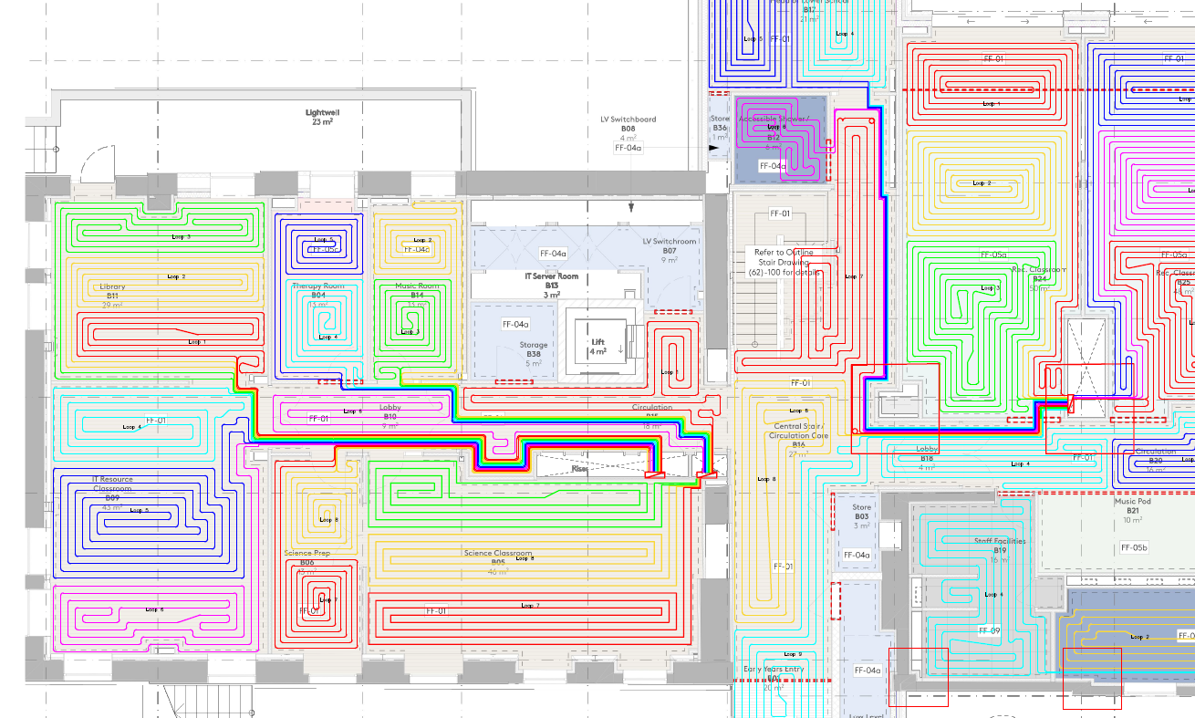
Not all UFH drawings are equal. A basic sketch showing pipe routes is useful for visualising the layout, but it falls well short of what a competent installer actually needs to commission a system correctly. Here's what a professional pipe layout drawing must include — and why each element matters.
Why the Drawing Quality Matters
UFH installers work from the design drawing. If critical information is missing or incorrect, one of two things happens: the installer makes assumptions (which may be wrong), or the work stops while the designer is consulted. Either outcome causes delays or errors that are expensive to fix once screed is poured.
The drawing is also the commissioning record. When a system is balanced, the flow rates and settings used should match the design. If those targets aren't on the drawing, there's nothing to commission to.
What Must Be on the Drawing
1. Pipe routes with fixing centres
The layout must show exactly how the pipe runs within each room — boustrophedon (snaking) or spiral — with the fixing centres clearly marked (e.g. 150mm, 200mm, 250mm). Centres determine the heat output per metre of floor, so they must match the heat loss calculation for each zone.
2. Circuit lengths
Every circuit must have its total pipe length calculated and stated on the drawing. This is critical for two reasons: it determines the pump head required to overcome resistance, and it's the basis for the materials order. Getting this wrong means either running out of pipe on site or laying circuits that are too long to balance properly.
3. Zone and circuit identification
Each circuit needs a unique ID that matches the manifold schedule. Without this, the installer cannot label manifold ports correctly — and balancing becomes guesswork.
4. Manifold position and port schedule
The drawing should show the proposed manifold location in each zone, with a schedule listing each port, which room it serves, the circuit length, and the target flow rate in litres per minute (l/min). This is what the installer uses to set the actuators and balance valves during commissioning.
5. Flow temperature and pipe specification
The design flow temperature (e.g. 45°C for heat pump, 55°C for boiler) and the pipe type (e.g. 16mm × 2mm PE-RT or PEX-a) should be stated on the drawing or in an accompanying design note.
What Happens Without a Proper Drawing?
Without circuit lengths, the installer estimates — often over-ordering pipe and under-specifying pump capacity. Without flow rates, the system is balanced by feel rather than by calculation. Without fixing centre data, the actual heat output of the floor may not match the design intent, leading to rooms that never reach temperature in cold weather.
These problems are rarely visible until the system is under load in winter. At that point, remediation usually involves digging up screeded floors.
Getting the Right Design from the Start
Hydronic Design produces installer-ready UFH pipe layout drawings as a standalone service (from £149) or as part of a Complete Design Package that includes heat loss calculations and manifold schedule. Drawings are produced in H2X and typically delivered within 48 hours of receiving your floor plans.
We work with contractors and installers across the UK — if you need a drawing in a specific format or need to incorporate a manufacturer's manifold spec, just let us know. Get in touch to discuss your project.